The electric bicycle controller is the “brain” or central nervous system of your ride, governing power delivery, safety, and overall performance. When the controller malfunctions, it can lead to frustrating issues such as sudden power loss, erratic throttle response, or the motor stuttering, compromising both your commuting efficiency and safety.
This comprehensive guide is designed to empower e-bike owners and mechanics with the knowledge to systematically diagnose common electrical system faults, understand the root causes, and implement preventive measures.

1. E-bike Electrical System Overview
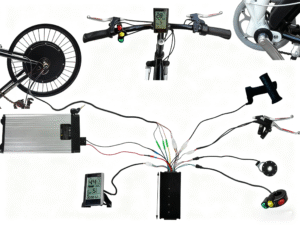
An e-bike’s functionality relies on a tightly integrated electrical ecosystem where key components communicate and manage power flow:
- Battery: The power source. Its Battery Management System (BMS) monitors voltage and current, often triggering protective shutdowns (a common cause of false controller faults).
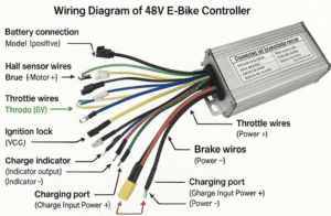
- Controller: The brain. It receives signals from the display, throttle, and sensors (like PAS and Hall sensors) and converts the battery’s DC power into the precise AC current required to drive the motor.
- Motor (with Hall Sensors): The Hall sensors within the motor relay rotor position feedback (Hall A, B, C) to the controller, enabling smooth, efficient power application.
- Display/HMI: Provides user interface, displays speed, battery level, assist modes, and transmits user commands (e.g., assist level changes) to the controller (Transmit Data, TX) while receiving system data (Receive Data, RX).
- Pedal Assist Sensor (PAS): Detects pedal rotation and sends a corresponding signal to the controller to initiate assistance.
- Wiring/Harness: The network of cables and connectors that transfer power and data signals between all components.
2. Common E-bike Electrical System Faults: At-a-Glance
Before diving into detailed troubleshooting, the table below provides a quick reference for common symptoms and their potential causes within the e-bike electrical system:
| Fault Point | Common Symptoms | Possible Cause | Diagnosis Priority | Auxiliary Checkpoint |
| Wiring/Plug Faults/Poor Contact | Power cuts out intermittently, motor stutters, erratic output | Loose connectors, bent pins, corrosion, frayed cables | High | Multimeter continuity test, visual inspection |
| Controller-Display Incompatibility | Display shows errors/no data, unresponsive buttons | Mismatched communication protocol (UART vs. CAN), firmware conflict | Medium | Check component model numbers, ensure vendor compatibility |
| Internal Controller Failure (MOSFET) | No response at all, overheating, motor fails to turn/runs rough | MOSFET burnout, internal component damage, liquid ingress | High | Multimeter resistance test (Phase to Battery +/-), internal visual check |
| Overload/Current Mismatch | Controller trips/shuts down, wiring or controller overheats | Controller max current exceeds BMS max current, components mismatched | High | Compare Controller/BMS/Motor spec sheets, measure actual current draw |
| Motor/Sensor/Hall Fault | Motor stutters/jitters, fails to start, “position error” code | Damaged Hall sensors, motor winding short, signal cable break | Medium | Multimeter Hall signal test (5V toggling), motor free-spin test |
| Water Ingress/Corrosion | Intermittent faults, problems after rain/washing, visible rust | Poor controller sealing (low IP rating), non-waterproof connectors | Medium | Check IP rating, open case for signs of moisture/corrosion |
| Battery/BMS Protection Trip | System suddenly cuts power under load, abnormal range | Battery low voltage, BMS overcurrent protection activation | High | Check stable battery voltage, compare controller current rating to BMS rating |
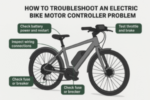
Recommended: How to Troubleshoot an Electric Bike Controller – Step-by-Step Guide
3. Detailed Fault Diagnosis and Resolution
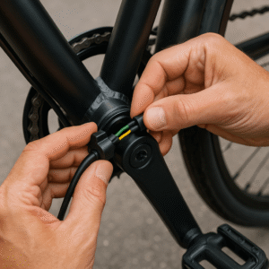
3.1 Wiring and Connector Faults (Loose Connections)
Symptoms: Often presents as intermittent power delivery, the motor cutting out suddenly, or highly inconsistent throttle response. Many suspected controller failures are actually simple wiring problems. Cause: Loose plugs, bent or oxidized metal pins (corrosion), or cables that are fatigued/broken due to movement and stress. Diagnosis:
- Visual Check: Inspect all plugs (motor, throttle, display, brakes) for frayed wires, bent pins, or signs of corrosion.
- Continuity Test: Use a multimeter (set to continuity mode) to check thin signal wires (like Hall or throttle signals) for breaks (an open circuit or “OL” reading). Prevention/Solution:
- Ensure all plugs are firmly seated.
- Apply dielectric grease to pins and connectors to repel moisture and prevent corrosion, making future disconnections easier.
- Secure wiring harnesses to prevent strain or chafing during riding.
3.2 Controller-Display Communication Protocol Incompatibility
Symptoms: The display may not power up, shows a blank screen, displays garbled data (incorrect speed/battery level), or buttons are unresponsive. Cause: The controller and display use different communication methods or protocols. Common protocols include UART (simple, point-to-point) and CAN Bus (a more complex, networked system). A mismatch in firmware or line sequencing prevents the necessary “digital handshake”. Diagnosis:
- Check the product specifications. If mixing brands, ensure they use the exact same communication protocol and line sequence. Solution: Always use controllers and displays designed to work together, ideally from the same manufacturer or a tested third-party match.
3.3 Internal Controller Failure (MOSFET Burnout)
Symptoms: The motor is completely unresponsive, runs very rough or only in certain phases, or the controller housing becomes excessively hot. Cause: Excessive current draw, thermal stress, or a manufacturing defect can cause a power transistor (MOSFET) to “blow” and often fail in a short circuit. Diagnosis:
- Free-Spin Test: If the motor is disconnected and spins normally, but encounters significant resistance (strong magnetic drag) when plugged into the unpowered controller, this often indicates a shorted MOSFET.
- Multimeter Resistance Test (Advanced): With the battery disconnected, use a multimeter (set to ohms/continuity) to check the resistance between the three motor phase wires and the controller’s main battery positive (+) and negative (-) terminals. A healthy circuit shows high resistance (e.g., 10kΩ). Zero or near-zero resistance (often accompanied by an audible beep on the multimeter) between a phase wire and the battery positive or negative terminal confirms a shorted MOSFET in that phase. Solution: If confirmed, the controller needs to be replaced. Repairs are possible but require specialized electronics knowledge.
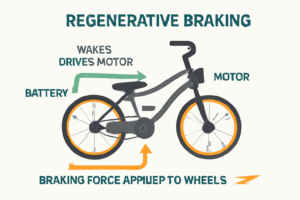
Recommended: Which Electric Bikes Have Regenerative Braking?
3.4 Overload and Component Current Mismatch
Symptoms: The system cuts power instantly during high-demand moments (e.g., climbing a steep hill), or wiring/controller housing feels extremely hot. Cause: The system is operating beyond its safe current limits. Crucially, if the controller’s maximum current rating exceeds the battery BMS’s maximum output current rating, the BMS will trigger an overcurrent safety shutdown to protect the battery. Diagnosis:
- Compare specifications: Verify that the controller’s voltage rating exactly matches the battery’s nominal voltage.
- Crucial Compatibility Check: Ensure the controller’s maximum Ampere (A) rating is equal to or lower than the maximum output current rating of your battery’s BMS. Solution: Use components with matched specifications. Avoid prolonged operation at maximum power/current.
3.5 Motor, Hall, or Position Sensor Fault

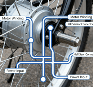
Symptoms: The motor “jumps” or “stutters” on startup, or the display throws an error code related to “position” or “Hall sensor fault” (e.g., E07/Error 24). Cause: Damaged Hall sensors inside the motor, a break in the thin signal wires, or a shorted motor winding. Diagnosis:
- Hall Sensor Test: Disconnect the motor from the controller. Use a multimeter (set to DC voltage, 20V range). Connect the negative probe to the sensor ground wire (usually black) and the positive probe to one of the signal wires (yellow, green, or blue). Slowly rotate the motor wheel. The multimeter reading should distinctly toggle between a low voltage (near 0V) and a high voltage (near 5V). Failure to toggle indicates a bad sensor or broken wire.
- Winding Test: Test the resistance between the three motor phase wires (with the motor unplugged). The resistance values should be very close to each other.
3.6 Water Ingress, Sealing Failure, and Corrosion

Symptoms: Intermittent failures that appear during or immediately after rain/washing, or visible signs of rust and moisture inside the connector shells. Cause: The controller enclosure or electrical connectors have inadequate waterproofing, allowing moisture to cause corrosion or short circuits. Prevention/Solution:
- IP Rating: When replacing components, opt for a controller with a high IP (Ingress Protection) rating, such as IPX5 (protected against water jets) or higher.
- Protection: Inspect the controller casing for damaged seals. Some components benefit from conformal coating (a clear polymeric film) applied to the circuit board for extra moisture resistance, though caution is advised with potting compound as it severely limits heat dissipation and repairability.
- After riding in wet conditions, open any covers and allow components to air out and dry.
3.7 Battery/BMS Protection Trip (The False Fault)
Symptoms: The bike suddenly loses all power, often under heavy load, leading the rider to mistakenly suspect a controller failure. Cause: This is often the BMS (Battery Management System) initiating a safety shutdown due to critically low battery voltage or an overcurrent event. Diagnosis:
- Check the battery charge level and terminals. Use a multimeter to confirm the battery is delivering stable, adequate voltage. A significant voltage drop under load suggests a connection issue or a failing battery/BMS.
Recommended: Nakto Electric Bike Reviews: Models, Value, Pros & Cons
4. The Quick E-bike Fault Diagnosis Checklist
Use this systematic flow to quickly pinpoint the problem, moving from the simplest checks to complex component testing :
| Step | Action | Focus |
| Step 1: Safety First | Disconnect the battery and power down the e-bike completely. Wait a few minutes to allow residual energy to dissipate. | Power safety |
| Step 2: Visual & Power Cycle | Inspect all visible wiring and connectors for obvious damage, looseness, or corrosion. Reconnect the battery; try a quick power cycle to clear minor software glitches. | External factors |
| Step 3: Battery Check | Confirm the battery is charged. Use a multimeter to verify it delivers stable, correct voltage to the controller’s input cables (e.g., 48-52V for a 48V system). | Power supply |
| Step 4: Check Sensors & Display | Check the display for specific error codes (e.g., E07 for Hall sensor, E25 for brake sensor). Verify that the brake levers are not stuck (which prevents motor activation). | Peripheral components |
| Step 5: Advanced Component Testing | If all external factors are ruled out, proceed to multimeter testing (Hall sensors, motor windings, and finally, MOSFET resistance tests) to confirm internal controller failure. | Core components |
5. Replacement and Maintenance Best Practices
Component Matching for Replacement
When a controller replacement is necessary, compatibility is paramount:
- Voltage Match: The new controller’s voltage (V) rating must precisely match the battery’s nominal voltage (e.g., 48V for 48V systems).
- Current Match (Safety): The controller’s maximum amperage (A) rating must be less than or equal to the battery BMS’s maximum output current to prevent system overloads and BMS trips.
- Protocol Match: The controller and display must use the same communication protocol (e.g., UART or CAN).
- Connector Type: Ensure the connectors (e.g., Higo, Julet) and wire colors/pin sequences match or can be correctly adapted.
Controller Replacement Tips
If replacing the unit, follow a structured process:
- Label Everything: Before disconnecting any plugs, label every connection clearly or take detailed photos. This prevents accidental miswiring during reassembly.
- Heat Dissipation: Ensure the new controller is mounted securely in the same orientation, preferably utilizing any cooling fins or thermal pads for adequate airflow and heat management.
- Testing: After reconnecting, perform a bench test (wheels off the ground) before riding. Check the PAS response by pedaling and verify that the brake sensors successfully cut motor power.
Prevention and Daily Care
Regular maintenance significantly extends the life of your e-bike electronics:
- Regular Inspections: Periodically check all plugs, particularly the motor and battery connections, for security and signs of moisture or rust.
- Avoid Overload: Limit continuous maximum power use, especially during steep climbs or sustained high-speed runs, to protect the MOSFETs from thermal stress.
- Water Management: Invest in controllers with high IP ratings. After wet rides, ensure the bike is properly dried off and allow covers to open and air out if possible.
Conclusion
While electric bicycle control system faults can seem intimidating, the majority can be resolved by systematically checking the peripherals (battery, wiring, connectors) before concluding the controller itself is the problem. By utilizing the quick diagnosis checklist and ensuring components are correctly matched and maintained, you can achieve reliable and safe e-bike operation for thousands of miles. Remember: record the fault symptoms, note any error codes, and always follow safety procedures by disconnecting the battery before starting any inspection or repair.